Stationary Decoder
Overview – What is a Stationary Decoder and What the heck is he building
In modern-day model railroading, we use DCC or Digital Command Control to allow discrete control over each train. This is accomplished by having a system that sends commands to specific addresses over the lines that power the track. Each engine on the railroad has a specific address and decoder and sometimes sound. The controllers/throttles send commands that ask a specific address to change speed, direction, blow the horn, turn on the light, etc. Decoders in each engine check the signal to see if the address matches its own and respond accordingly if true. This allows massive control over the entire railroad, as many engines as there are addresses, and as many controllers needed. At Rockledge Model Railroad Museum, we often have 100+ engines and 30+ people simultaneously being controlled.
So what the heck is a stationary decoder, A stationary decoder is as its name suggests, a decoder that does not move. It works the exact same way the decoders in the engines, by reading the DCC signal but often have different functions such as controlling switches, signals, lights, relays.
Using this I created a Stationary Decoder, to allow for discrete control over 12 servos controlling and monitoring of 12 switches. This allows the ability to throw or report position on any control device anywhere that is on the DCC system. A dispatcher can be created, who can sit in an area with a view of the entire railroad and monitor and deny and give access to switches and command over the railroad. We try and emulate not just the rails but an entire railroad system.
Version 2 – Design Files
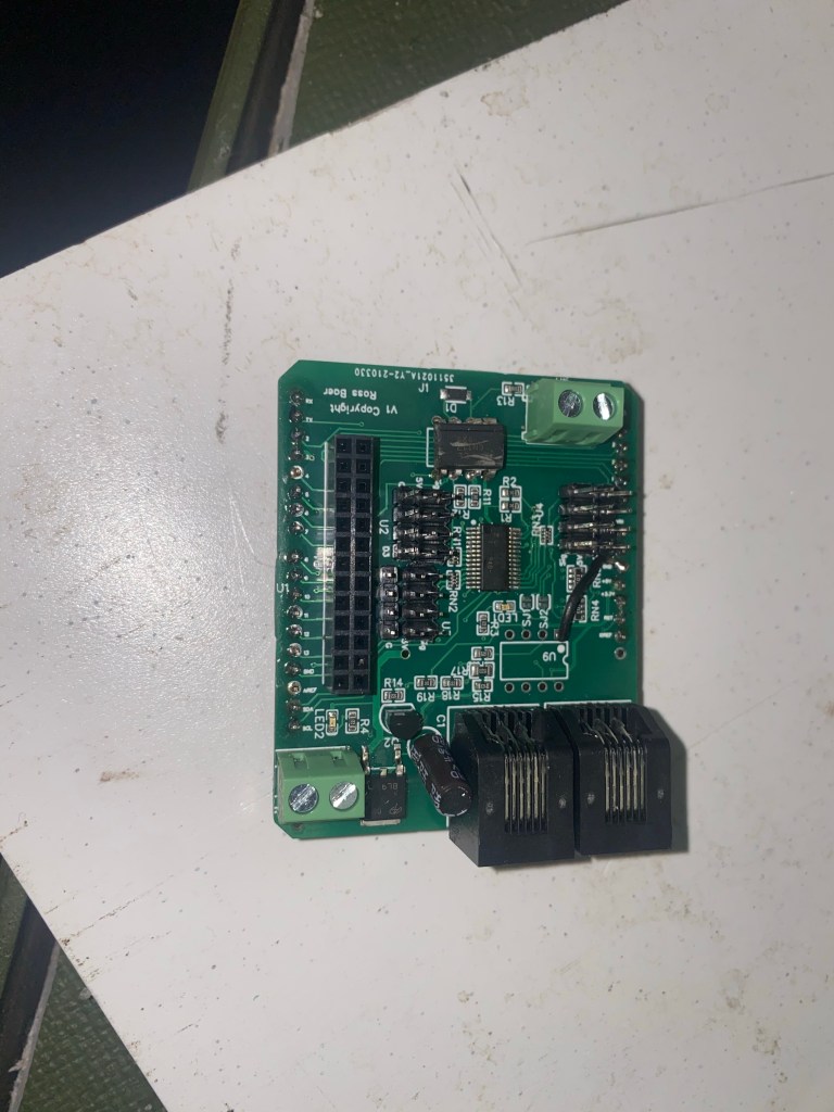
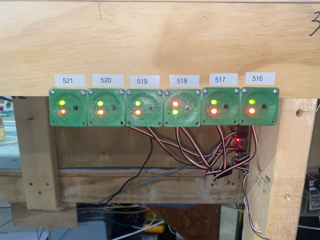
Servo board V2 implemented

A single V2 board mounted for testing
Description
This board is mounted by itself and was the first unit of the V2 deployed. As you can see the Loconet cable (White-left side) and Power cable ( left side) divide the board from the servos on the right side. This allowed for ease of installation and troubleshooting
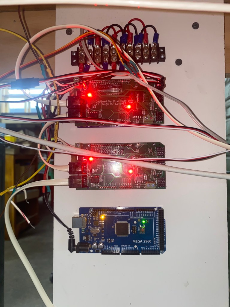
Multiple V2 boards deployed in tile configuration
Description
Here you can see adding multiple units in a vertical stack allows for a simple chain of input cables on the left side. This is because each unit takes the exact same power and loconet so I am able to create a distribution block at the top for each of the power and link the loconet between each unit. while keeping the servos on the other side, thus creating an easier system to implement and troubleshoot.
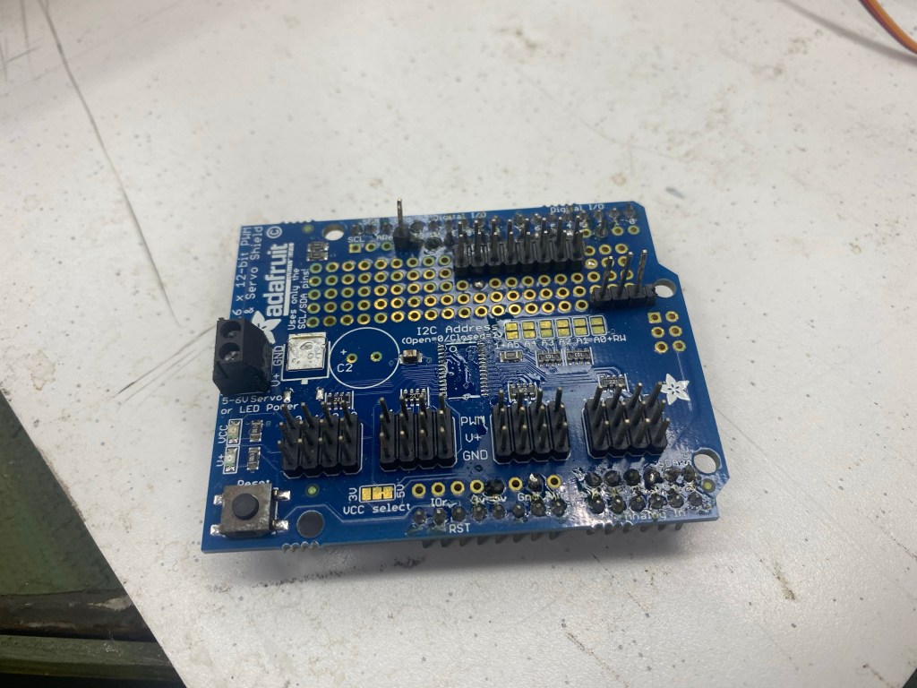
Servo Board v2

How the boards come from the manufacturer
Description
These boards due to supply restrictions also did not include the PCA9685, therefore I again surface mounted the PCA9685. Furthermore, I assembled the remaining pin needed for the servos and connection to the mega. These boards are larger and easier to assemble as spreading out the comments allowed for more room to solder.
LocoNet vs DCC
LocoNet vs DCC
Description
The difference between loconet and DCC is the way it operates. DCC is the signal sent through the rails to the decoders in the engines or stationary decoder boards like mine. These Signals are often read-only and broadcast over the who system. This means that decoders can only read and are unable to report positions back to the system. Loconet however is for throttles and controllers to send commands to the track along with sending broadcasts for requests. Therefore by using the loconet I can decode the packets to look for any switch machine request and then check the address to see if it matches. Furthermore, the loconet allows me to report positions back to the system when the servos are manually thrown or during the start-up sequence to ensure that the system knows the current position of the switches. This allows for complete and remote control of the switches from a dispatcher who can monitor the positions. The loconet has another advance when a short occurs on the track the breaker shuts off the power, this includes the signals of DCC, thus if a switch was too short you would be unable to throw the switch remotely and would be required to use the corresponding toggle
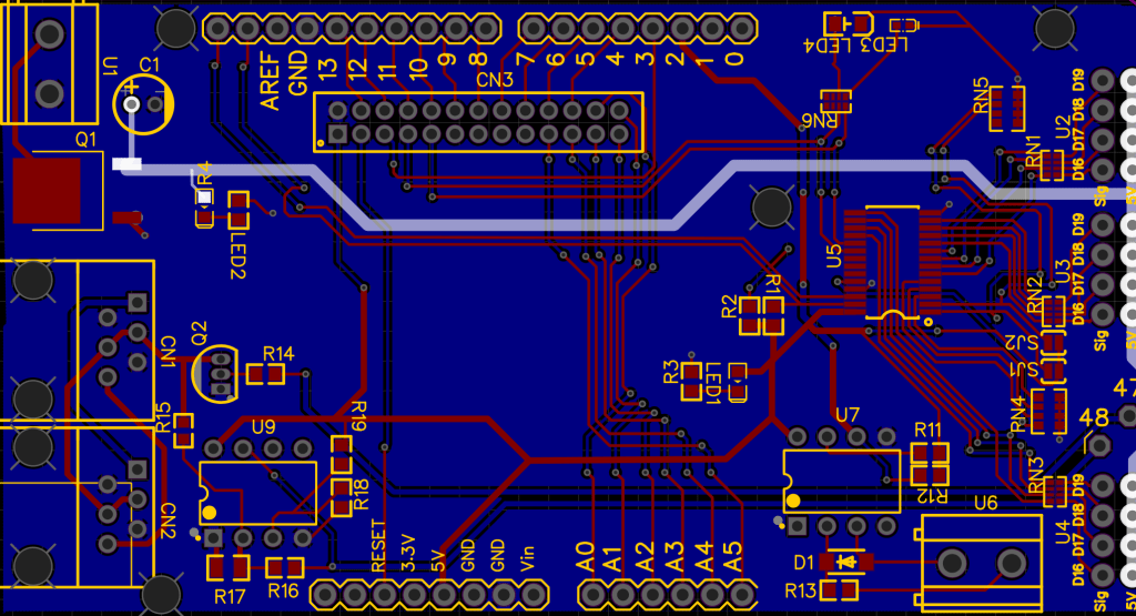
Servo board V2 PCB design
V2 PCB design
Description
This design separates the servo movement to the left and the power and loconet to the right. This allows for the ability to easily chain the units together as the power and loconet can be strung between each unit with small jumpers and the servos come in on the complete another side thus separating inputs and output. Lastly, the input/breakout cable slot move and now uses a 26 pin locking cable to prevent the cable from being pulled out.
Servo board V1 Fixes to V2
Wiring schematic for fixes
Description
The first fix was to upgrade from a UNO to a Mega, this allowed me to increase my processing power and storage. This fixed the issue of crashing and corruption of controllers. Nextly using a mega I was able to use a bigger shield to allow for more room. Furthermore, the loconet issue was due to the wrong port on the Arduino being used. On V1 the output for the locnet was on pin 2 however it required to be on pin 7, creating interference on the loconet system. When moved to a mega the loconet pins were moved to 47 and 48 respectively.
Servo board V1 problems
Designed to fix issues
Description
Some of the common issues of the first designed PCB were that the servo slots were often very hard to find and troubleshoot if the servo was not moving. Furthermore, the DCC connection was often disconnected easily. In addition, the UNO often would crash due to a lack of ram and storage. Lastly, the LocoNet ports would crash the entire system and would need to be disconnected for the layout to regain function.
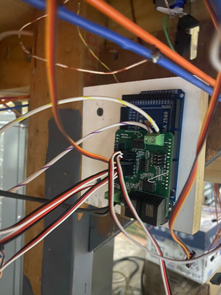
Servo Driver Board v1 implementation
Picture of the Servo board under the layout
Description
A mounted board on an Uno, this current controller runs 8 servos and 4 of them are in a route for the ladder. This controls the end of the Norristown area on the layout. I was able to implement 4 of these devices for testing and getting feedback to fix common problems.
Servo Driver Board v1 made
Completed board after mounting the PCA9685 and pins
Description
These are the first version boards that I ordered, These PCB boards arrived without pins for the servos or Arduino or the PCA9685. I was able to easier solder on the pins. I ordered the missing PCA9685 servo drivers and using a heat gun and solder past carefully surface soldered the chips on the board.
Servo Driver Board v1 PCB desgin
Design mapping of the PCB
Description
Following the schematic, I organized the components into their sections. We have the DCC track, Loconet testing, Servo Driver and servo pins, Input/breakout slot. These allowed for the best control and the PCB was designed to fit on top of an Arduino Uno. I tried to organize the sections to limit the number of long trace runs that clutter an already busy board.
Servo Driver Board v1 schematic
Schematic for the first custom PCB board
Description
Combining all of the electronic pieces from the prototype board I was able to create the first schematic, I also used a loconet interface for testing. This schematic not only incorporated the servo controller but the DCC coupler and manual inputs. Along with adding LED power indication.
Prototype V2 Coding Changes
Mainline defaults
Description
Along with adding DCC to the board, I also added some functions that allowed my board to start providing functions that arent possible on the Tam-Vally controller. When the railroad is turned on when members come in, the coil machines reset to a default position, we use this default position as the straight mainline. SO that you are able to walk in and run a train around without having to make sure each switch is in the normal position ( we have well over 600 switches). So to recreate this function on the board, I used a startup sequence to check to see if each servo is enabled with a default, and then move the servo to its default position. The Tam-Vally does not allow this, which had led to accidents already.
Route control
Description
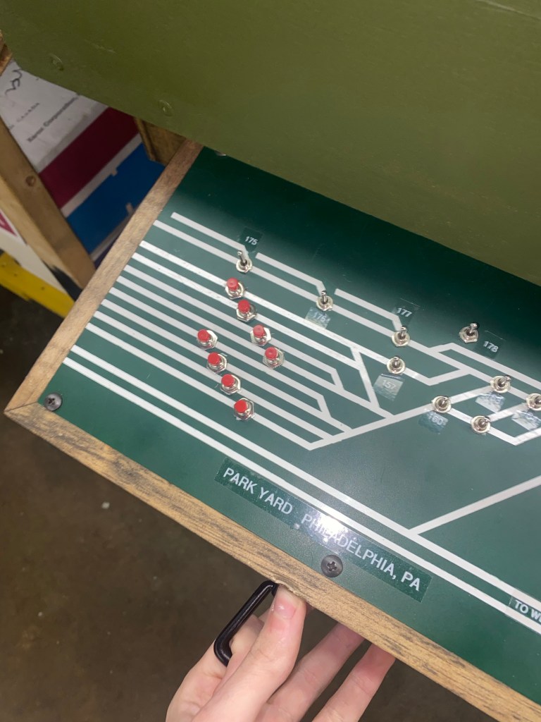
In complex areas like yards where there is a ladder of switches, we often use a route or matrix to throw multiple switches for the desired track. For example, if we have 5 tracks in a yard and you would like to enter track 3. Rather than throw each individual switch to line it up, we can use a route to throw the corresponding switches for the track. With the coil machines, we used a push button for each track and a diode matrix to activate the correct positions on the machines. I was able to recreate this matrix for the servos, by creating a route code that you can enter each servo and direction needed. When activated by a single input or any direct request from DCC allowed for the creation of yard ladders that functioned exactly like the coil machines.
Prototype V2

prototype v2 included the DCC add-on board
Description
Combining the DCC board, and minor changes for prototype v1 created version 2. This had the capabilities of not only throwing the servos from a toggle input from a panel but also being able to read throw commands requested over the track.
DCC add-on board

The add-on board for a DCC interface for an Arduino
Description
Once I was able to have the Arduino read and react to the DCC command I used a prototype board to create a board that had the inputs from the track and an output cable to connect to the Arduino to enable DCC control of switches. These boards followed the schematic below and were mounted in a simple case to help reduce damage or disconnection. This board allowed expansion from prototype V1 to V2
DCC control Code and Input
Code and Arduino serial monitor for DCC input
Description
Using this code I was able to read the DCC packets going through the rails and pick out the packets that were intended for switches and then compare the address requested to the addresses programmed on each unit
DCC control test

The schematic for a DCC interface for a arduino
Description
After successfully deploying a servo controller, I moved on to advancing it capabilities. Now that the controller can take a manual input from a toggle on a board, I figured I had to be able to control the servos through a command. There are 2 ways, read the DCC signal going through the rails or read the packets on the loconet. I decided to first use the DCC as it was the simplest and required common parts that I was able to pick up at micro center. This included a highspeed optocoupler to ensure that the 12v square wave from the track didn’t touch the 5v from the Arduino. Using the schematic I was able to test and read the DCC signal from the track using a breadboard. After being able to read the switch position commands sent over the track I was able to create an add-on board that enables DCC functionalityityity on my units.
Prototype V1
An Adafruit PCA9685 shield for UNO/MEGA
Description
For the first prototype, I had to start on the basics. First was servo movement and input triggers for the servo movement. I used header expansions in the open breadboard area on the shield to tap in inputs 13-4 and analog 0-6 (Inputs 14-19). This gave me 16 input channels to use, and each servo had normal and thrown positions, thus leading to 8 individually togglable servos. Since I was able to give each servo a dual input for the directions allowed me to continues using the On/off/on momentary toggles that were used for the analog machines. Therefore the panels for servo controls would be the same as the ones that control the analog machines. Using a break outboard I was able to combine the common and separate each servos input to 3 pin connections. This allowed me to implement the first servos and controller completely designed for the club. This controller is still in use after 2 years and still functions perfectly.
Tam Vally controls vs Analog standards
Tam-Vally push buttons vs coil control panel
Description
The Tam-Vally controller uses its own design push-button systems to trigger the servos to move side to side. The movements side to side can also be triggered by a coconut enable device, such as a throttle or phone which can call for the particular switch number to be thrown. However the analog coil machines are not integrated with LocoNet capabilities, they only move when activated by the switch on the panel connected. Being LocoNet enabled was a key selling point for the controllers as it allowed for control from any device that is connected at any location, thus allowing central control from a dispatcher. Nevertheless, the controller’s way of numbering proved to be difficult. If the first switch was 516 the following switches had to go up in number to work. You weren’t allowed to provide specific addresses for each servo. Furthermore, the controller lacked the ability to tie together 2 servos with individual positioning. I started prototyping my own servo controller that would fix all of tam valleys lacking areas and tailor it to exactly what the club needed
Servo Mount Fixes

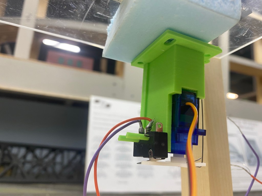
Comparison between TamVally mount and My Design
Description
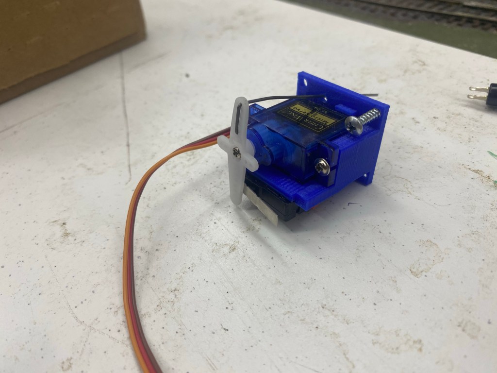
After disassembling a tam valley mount and prototyping for a better mount, I realized that if I increased the distance from the servo arm and fulcrum of the pivot that it would take a larger movement of the servo arm to move the same distance of the frog points. This accomplishes two things, gave a strong throw due to the mechanical leverage along with providing the time and distance necessary for the servo to engage the microswitch while the points are traveling in between the rails. This solved the servo mounts and after testing proved stronger, more reliable, and cheaper since I was able to fabricate them at home with my 3D printer. Thus reducing the cost of the units.
Issues with Tam-Valley Servo and Mounts
TamVally depot servo and mount with micro switch
Description
As we started to deploy the tam-valley-based servos we found that as the servos were moving from side to side, the microswitch activation for the frog polarity was accruing too late. The points of the switch would collide with the opposing rail before the polarity was flipped causing a momentary short and tripping the breaker for the entire section
Tam-Vally Stationary Decoder
TamVally depot provides a loconet compatible servo controller to move the switches
Description
Tam-Valley depot offers a octo-controller that can control up to 8 individually controlled servos. This controller is one of the options available to purchase, these are compatible with their designed servos and mounts which include a microswitch for the frog. This controller used tam -vally own pushbutton style controlling and often is very clunky and doesn’t react fast enough. These units are also hard to program and cost $60 for the controller and another $70 for the accessories needed just to use them
Old Analog Machines
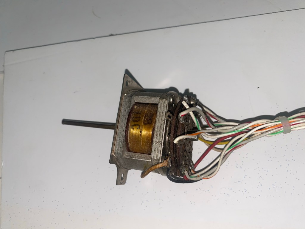
These Machines are from world war 2 bombers, here is one unmounted
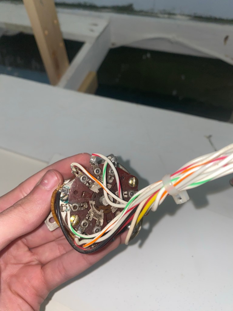
Description
Since the old layout these 28v rotating coil machines, have been used to throw the switches side to side. They use a coil and corresponding latching/holding resistor to hold in the thrown position. We use guitar or 25thou steel wire to provide the lateral movement from the rotating shaft to throw the switch. The machines also have sets of NO/CO/NC contacts controlled when thrown. We use these to change the polarity of the frog so that the trains are able to pass through both directions. The Machines only have 2 positions and 1 speed, they tend to be temperamental if not installed correctly, and will chatter and not lock into positions. I have worked extensively with the members to ensure reliability with these machines, however, these machines are analog and must be thrown by hand or by a corresponding switch.